

Precision Injection Molded Automotive Components Engineered for Faster Production
Injection molded automotive components are the backbone of modern vehicle manufacturing. This process works by forcing molten plastic into a steel mold at high pressure, creating exact parts like dashboards and bumpers in seconds. The real benefit is that it delivers incredibly durable, lightweight pieces that snap together perfectly the first time—saving both weight and assembly effort. Simply design a part, create the mold, and let the machine produce thousands of identical, ready-to-use components with tight precision.
Precision Crafting: The Evolution of Molded Parts in Modern Vehicles
Precision crafting in injection molded automotive components has evolved from simple trim pieces to complex, load-bearing structural elements, driven by advances in mold design and material science. Modern multi-shot molding allows for rigid substrates to be seamlessly overlaid with soft-touch polymers, eliminating secondary assembly. The key insight lies in the tolerance control now achievable:
Today’s injection molding holds critical dimensions within micrometers, enabling direct replacement of stamped metal brackets and housings with lighter, corrosion-resistant plastic equivalents.
This precision extends to integrated sealing lips and living hinges, crafted directly into a single part. By utilizing gas-assist and rapid cooling channels, cycle times have shortened while part consistency has skyrocketed, fundamentally redefining what a single molded component can achieve under the hood or inside the cabin.
From Metal to Polymer: A Historical Shift in Manufacturing
The shift from metal to polymer in automotive manufacturing began as engineers sought weight reduction without sacrificing structural integrity. Early injection molded parts replaced heavy steel brackets and housings with polyamide and polypropylene components, cutting vehicle mass significantly. This transition required retooling dies for high-pressure plastic flow and redesigning geometries to account for polymer shrinkage and creep. Early adopters faced challenges with thermal expansion mismatches between plastic parts and metal assemblies, necessitating revised tolerance stacks. The historical shift in manufacturing ultimately enabled complex, multi-functional parts like integrated intake manifolds that were impossible to cast in metal.
- Lower density polymers reduced component weight by 30-50% compared to stamped steel.
- Injection molding eliminated secondary machining operations required for die-cast metal parts.
- Polymer corrosion resistance extended part lifespan in underhood environments.
Key Material Families Driving Performance and Weight Reduction
Three material families dominate performance and weight reduction in injection molded automotive components. High-performance engineering thermoplastics, such as polyetheretherketone (PEEK) and polyphthalamide (PPA), replace heavy metal housings and structural brackets while withstanding underhood temperatures and chemical exposure. Continuous fiber-reinforced thermoplastics (CFRTPs) deliver steel-like rigidity at a fraction of the mass for semi-structural parts like front-end modules. Polypropylene (PP) compounded with long glass fibers offers an unbeatable balance of low density, impact resistance, and cycle-time efficiency for large interior and exterior panels, directly cutting vehicle weight by up to 30% versus conventional materials.
Key material families—engineering thermoplastics, CFRTPs, and glass-filled PP—drive performance by replacing metals while reducing weight, enabling lighter, stronger molded automotive components.
The Role of Thermoplastics vs. Thermosets in Under-Hood Applications
Under the hood, thermoplastics vs thermosets in under-hood applications boils down to heat resistance versus design flexibility. Thermosets, like epoxy, handle constant engine heat above 200°C without softening, making them ideal for valve covers and oil pans where structural integrity is non-negotiable. Thermoplastics, such as nylon, melt if overheated but offer lighter weight and easier recycling; they shine in air intake manifolds and coolant reservoirs where moderate heat meets complex geometries. Thermoplastics creep under sustained load, so fasteners must account for that with metal inserts. Your choice hinges on whether the part sees steady inferno-level heat or occasional warm-up cycles.
Thermosets hold up to extreme heat but are brittle and hard to recycle; thermoplastics are lighter and more adaptable but can soften near the engine block.
Designing for Durability: Structural and Aesthetic Considerations
Designing for durability in injection molded automotive components means balancing structural integrity with lasting aesthetics. For the structure, you integrate ribs and gussets to distribute stress without increasing wall thickness, preventing warpage under heat and vibration. Aesthetic durability relies on UV-stable pigments and a matte texture to hide minor scratches from daily use. Q: How do you avoid sink marks on visible panels while keeping them tough? A: Use a core-cavity cooling strategy and a gradual wall transition, so the plastic packs evenly without visible defects.
Wall Thickness and Rib Design for Crash-Relevant Components
For crash-relevant components, wall thickness must be precisely optimized—too thin risks brittle fracture under impact, while excessive thickness creates sink marks and uneven cooling. Ribs, strategically placed to direct energy absorption, require a thickness of 50-60% of the nominal wall to avoid local stress raisers. Their layout should follow load path vectors, tapering radii to prevent shear failures. This balance ensures progressive collapse rather than catastrophic shattering. Controlled rib geometry dictates whether a pillar crushes predictably or snaps.
In crash-relevant injection molded parts, wall thickness and rib design converge to manage energy dissipation: ribs guide deformation, while uniform wall sections prevent weak points that compromise occupant safety.
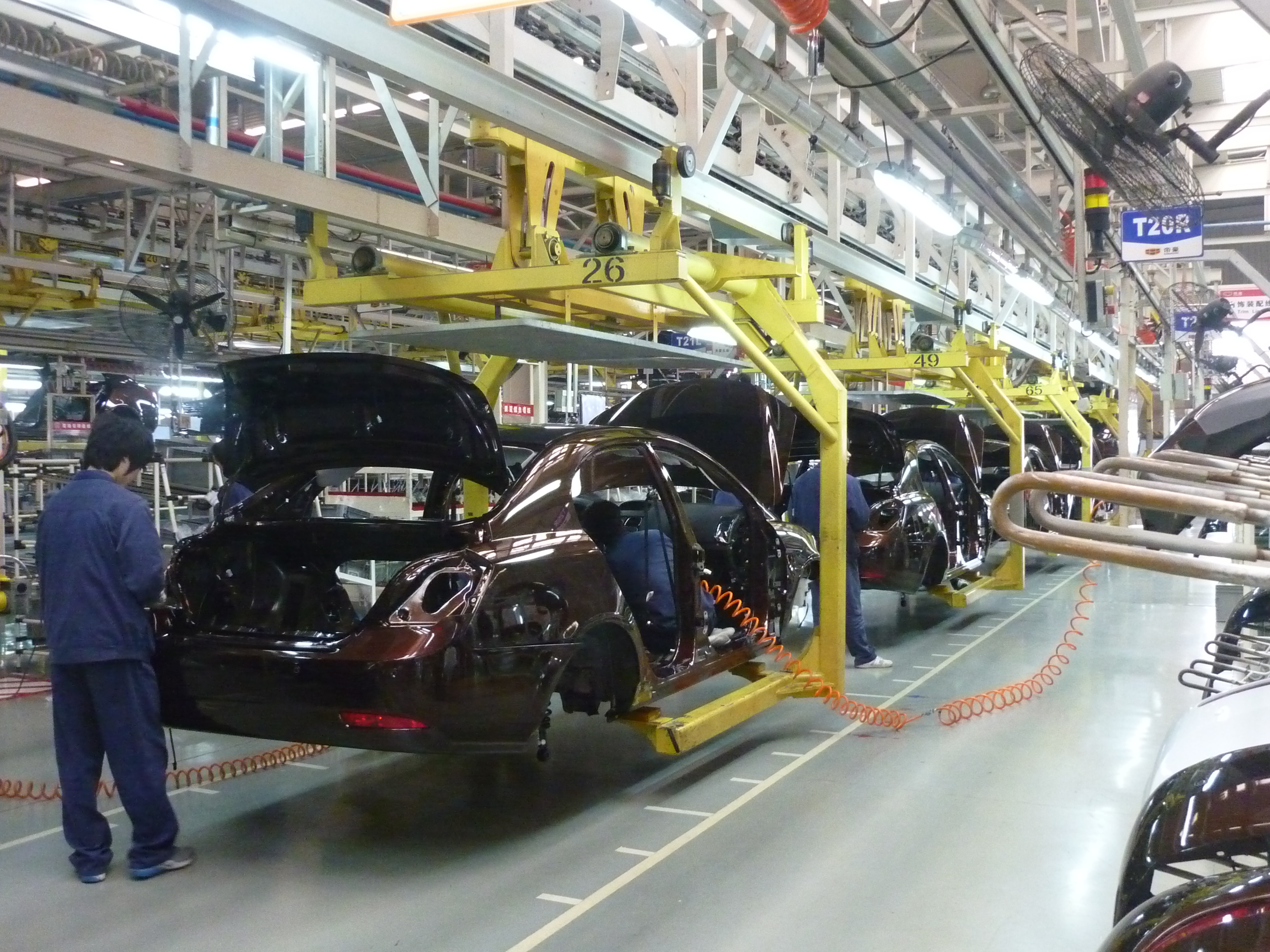
Surface Finishes and Texture Molding for Interior Cabin Appeal
Surface finishes and texture molding directly determine the tactile and visual quality of interior cabin components. By integrating grain, leather, or soft-touch textures directly into the mold cavity, manufacturers eliminate secondary painting or coating steps, enhancing durability against scratches and UV exposure. The logical sequence for achieving consistent appeal involves controlling steel or laser-etched textures to avoid sink marks or gloss plastic injection molding automotive parts mismatches. Texture consistency across complex geometries ensures the cabin feels cohesive, reducing glare and improving perceived quality. To achieve this:
- Specify texture depth and pattern orientation in the mold design phase.
- Optimize melt flow temperature and injection pressure to replicate fine surface details.
- Use mold texturing to mask flow lines or knit lines from gating.
Tolerance Management in Complex Geometries for Assembly Fit
Managing tolerance in complex geometries is critical for ensuring flawless assembly fit of injection molded automotive components. Curved interior panels and interlocking bezels demand precise geometric dimensioning and tolerancing (GD&T) to compensate for warpage and shrinkage. Practical strategies include designing for selective compliance, using living hinges or snap-fits that absorb minor deviations without compromising alignment. Finite element analysis during mold design predicts where stress will distort a part, allowing engineers to add stiffening ribs or adjust gate locations.
Q: How do you handle tolerance stack-up in a multi-part dashboard assembly? A: By integrating reference datum points and using virtual simulation to balance each component’s real-world shrinkage, ensuring interference-free fit during thermal cycling.
Process Innovations That Shape Quality and Efficiency
In injection molded automotive components, process innovations directly enhance quality by enabling precision control over material viscosity and cavity pressure. Real-time adaptive process control systems automatically adjust injection speeds and packing phases, reducing warp and sink marks in complex geometries like air-intake manifolds. Mucell microcellular foaming reduces clamping force requirements while eliminating sink marks, improving dimensional consistency. This also shortens cycle times through faster cooling, boosting efficiency. Simultaneous use of conformal cooling channels, printed via additive manufacturing, ensures uniform thermal distribution, preventing hotspots that cause part distortion. These methods minimize scrap rates and rework, delivering high-quality structural components with repeatable properties.
Gas-Assisted and Water-Assisted Molding for Hollow Sections
For automotive components requiring hollow sections, such as intake manifolds or fluid-handling ducts, gas-assisted and water-assisted molding eliminates the need for core pulls. Injected gas (typically nitrogen) or high-pressure water follows the plastic melt, forming smooth, continuous internal cavities while significantly reducing part weight. Water offers faster cooling, cutting cycle times by up to 80% on thick-wall sections, whereas gas provides greater flexibility for complex geometries. Both methods drastically reduce sink marks and warpage by packing the part against the mold cavity, ensuring superior dimensional stability and eliminating secondary drilling operations.
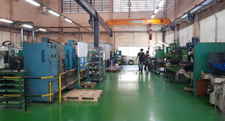
Gas and water injection create precise, lightweight hollow channels in automotive parts, reducing material use while preventing warpage and improving cycle efficiency.
Multi-Shot and Overmolding Techniques for Seals and Grips
Multi-shot and overmolding techniques transform seal and grip production by bonding distinct materials in a single cycle. A TPE overmold onto a rigid polypropylene core creates soft-touch handles that resist fatigue, while multi-shot processes sequentially inject a resilient elastomer for lip seals against a harder carrier. This eliminates secondary assembly, ensuring perfect alignment on gearshift boots and weatherstrips. The result is seamless multi-material adhesion that prevents delamination under heat or vibration, directly enhancing durability in door handles and steering-wheel grips.
Overmolding and multi-shot processes fuse soft seal and grip layers directly onto rigid substrates, eliminating assembly steps and boosting long-term performance in automotive components.
Real-Time Process Monitoring and Adaptive Control Systems
In injection molding automotive components, real-time adaptive process control continuously monitors cavity pressure and melt temperature to counter viscosity shifts. The system instantly adjusts pack and hold phases, eliminating short shots or flash before they solidify. This closed-loop regulation directly reduces dimensional variation in safety-critical parts like airbag housings. By compensating for material batch inconsistencies, it minimizes scrap without operator intervention.
- Sensors detect pressure deviations within milliseconds to trigger barrel temperature corrections.
- Adaptive algorithms modify injection speed profiles to maintain consistent fill rates.
- Automatic hold pressure adjustment compensates for mold temperature drift from cycle heat buildup.
- Real-time viscosity monitoring prevents off-spec parts from reaching the trimming station.
Material Selection Strategies for Thermal and Chemical Resistance
The engineer knew the engine bay component had to survive both blistering under-hood heat and aggressive coolant leaks, so the material selection strategies for thermal and chemical resistance began by screening high-temperature thermoplastics. Polyphthalamide was chosen for its ability to withstand continuous 180°C exposure while resisting ethylene glycol and oils. Prototyping in glass-filled PPA revealed that crystallinity levels directly impacted chemical barrier performance, forcing a mold temperature optimization to lock in the right structure. For a nearby fuel system clip, material selection strategies for thermal and chemical resistance pivoted to PPS, which shrugged off hydrocarbon swelling and creep at peak soak temperatures. The molder learned that drying parameters for PPS were non-negotiable—moisture during injection created voids that turned chemical resistance porous under pressure cycling.
High-Heat Polymers for Engine Compartment Enclosures
For engine compartment enclosures, high-heat polymers like polyphenylene sulfide (PPS) and polyphthalamide (PPTA) are selected based on their continuous service temperature above 180°C and resistance to hot oil, coolant, and road salts. These materials maintain dimensional stability under hood while withstanding thermal cycling without embrittlement. The high-heat polymer selection prioritizes glass-transition temperature and hydrolysis resistance to prevent cracking at wiring harness interfaces or bolt bosses. Fillers such as glass fiber further enhance creep resistance under sustained clamping loads near exhaust manifolds.
High-heat polymers for engine compartment enclosures balance thermal stability above 180°C, chemical resistance to automotive fluids, and dimensional integrity under cyclic stress.
Flame-Retardant Compounds for Electrical Housings and Connectors
For injection molded automotive components, flame-retardant compounds for electrical housings and connectors must meet specific UL 94 V-0 or 5VA ratings to prevent fire propagation from short circuits. These materials typically use halogenated or phosphorus-based additives to suppress ignition without compromising dielectric strength. Polyamide 66 with glass fiber reinforcement offers a balance of creep resistance and continuous use temperature up to 130°C, while PBT provides superior dimensional stability for pin retention. The chosen flame-retardant compound formulation must maintain flow characteristics for thin-wall connector geometries and resist hydrolysis under hood. Phosphinate-based systems are often preferred for their low smoke density and compatibility with lead-free soldering processes.
| Property | Halogenated FR Compound | Phosphinate FR Compound |
|---|---|---|
| Flame rating | UL 94 V-0 at 0.4mm | UL 94 V-0 at 0.8mm |
| CTI (Comparative Tracking Index) | 400-500V | 500-600V |
| Typical application | Sensor housings | High-voltage connectors |
UV-Stablized Formulations for Exterior Trim and Lighting
For exterior trim and lighting components, UV-stabilized formulations are essential to prevent photo-oxidative degradation and chalking from prolonged sun exposure. Select ASA or impact-modified PMMA for pillar trims and light housings, as these provide inherent UV resistance without a painted topcoat. For lighting lenses, acrylics or UV-stable polycarbonate with hindered amine light stabilizers (HALS) and UV absorbers maintain clarity and prevent yellowing over the vehicle’s lifespan. The chosen material must also retain its impact strength at low temperatures. Properly compounded UV-stabilized UV-resistant polymer blends ensure colorfastness and surface integrity in mirror housings and side moldings, directly addressing thermal expansion and chemical attack from road salts without delamination.
Advancing Lightweighting Through Component Consolidation
The engineer studied the sprawling assembly drawing, a tangle of steel brackets and fasteners, then visualized a single injection-molded polyamide component. By consolidating those ten parts into one mold, the door module shed 40% of its mass. Every eliminated fastener hole and weld bead becomes a direct weight reduction, as the plastic flows into complex geometries that metal simply cannot form. This consolidation also slashes assembly time, removing tolerance stacks that previously required shims and adjustments. A passenger door that once took minutes to assemble now clicks together in one streamlined operation, its lighter frame allowing a smaller, more efficient window regulator motor to be specified.
Integrating Brackets, Mounts, and Ducts into Single Molds
Integrating brackets, mounts, and ducts into a single mold eliminates separate assembly steps and reduces potential failure points in the vehicle structure. By merging these load-bearing and airflow components into one part, engineers achieve a unified geometry that distributes stress more evenly while saving significant weight. Advanced gas-assist molding allows for hollow duct channels within the same tool, maintaining air flow without adding material. The challenge lies in balancing cooling rates across varying wall thicknesses to prevent warpage in complex bracket-to-duct transitions.
- Consolidates multiple fasteners and welding points into one continuous plastic part.
- Requires precision gate placement to ensure consistent fill around duct voids and bracket ribs.
- Eliminates tolerance stacking from separate mounts, improving fitment and NVH performance.
Reducing Assembly Steps via Snap-Fit and Self-Locating Features
By integrating snap-fit assemblies and self-locating features directly into injection molded automotive components, manufacturers eliminate fasteners, adhesives, and secondary alignment fixtures. A single molded part can incorporate cantilever hooks, compression bosses, or guide ribs that precisely lock adjacent panels together during final assembly. This consolidation removes both the manual labor of inserting clips and the quality risks of misaligned sub-components. The result is a faster, more repeatable production line where each snap action confirms correct placement, reducing total assembly steps and associated cycle time without sacrificing structural integrity.
Case Studies: Aluminum Replacement in Bumper and Chassis Parts
Specific case studies demonstrate that replacing stamped aluminum bumper beams with glass-filled nylon injection molded components achieves a 35–40% weight reduction while maintaining impact performance. For chassis crossmembers, short-fiber reinforced polyamide molds consolidate multiple aluminum stampings into a single part, eliminating welding points. One validated study shows a hybrid bumper design using a molded polymer core with steel inserts passing 8 km/h pendulum tests. Another case on a front-end module replaces seven aluminum brackets with one injection molded carrier, reducing assembly steps by 60% and improving torsional stiffness by 12% due to optimized rib geometry.
Quality Assurance Protocols for Safety-Critical Moldings
The hum of the press changes pitch as a dashboard beam, destined for a frontal impact zone, drops onto the inspection table. Our quality assurance protocols for safety-critical moldings kick in instantly. A laser scanner compares every millimeter of the beam against the CAD master, flagging a 0.05mm deviation in a rib that must fracture precisely upon collision. Reject. The operator pulls the next shot, but the protocol doesn’t stop at geometry. A process capability study on melt temperature, logged from the previous ten thousand cycles, links this deviation to a worn check ring. The line halts, not for a recall, but for a preemptive tool change—ensuring the next thousand parts will crush exactly as designed, protecting the passenger who will never see this part but depends on it.
Dimensional Validation Using Coordinate Measuring Machines
For safety-critical moldings like airbag housings, dimensional validation using CMMs catches even micron-level warp. The process starts with fixturing the part in the same orientation as its final assembly. Next, the probe touches critical datums—bosses, snap-fits, and sealing surfaces—checking against the CAD model. A focused sequence streamlines this:
- Load the part and align it to its datums.
- Probe critical features tied to function, like wall thickness and hole positions.
- Review the deviation report for any out-of-tolerance points.
This catches tool wear early, letting you adjust before defective parts reach the line.
Mechanical Testing for Impact and Fatigue Resistance
For injection molded safety components, mechanical testing for impact and fatigue resistance validates long-term durability against real-world loads. Charpy or Izod impact tests assess a part’s ability to absorb sudden force without brittle fracture, critical for brackets and housings. Fatigue testing then subjects the molding to repeated stress cycles, simulating years of vibration or thermal cycling in minutes. A servo-hydraulic actuator applies programmed loads while the part is monitored for crack initiation. How does fatigue testing determine a component’s safe service life? It identifies the stress level at which the material fails after a specific number of cycles, allowing engineers to set accurate replacement intervals and avoid catastrophic failure.
Leak Testing and Burst Pressure Limits for Fluid Handling Parts
For fluid handling parts, quality assurance centers on certified burst pressure verification to guarantee safety under extreme operating conditions. Leak testing employs trace gas detection or pressure decay methods, isolating micro-leaks that could cause system failure. Burst limits are validated through hydrostatic testing, with acceptance criteria set 150-200% above maximum working pressure to account for material fatigue and thermal cycling. This ensures the part maintains integrity during sudden pressure spikes without catastrophic rupture.
- Helium mass spectrometry detects leaks as small as 1×10⁻⁶ mbar·L/s, identifying defects invisible to standard methods
- Burst pressure thresholds are derived from finite element analysis correlating weld-line strength and wall thickness variations
- Production samples undergo random burst tests at 2.5x design pressure to confirm safety margins
Sustainability and the Circular Economy in Plastic Part Production
Injection molding for automotive components now closes the loop through circular economy in plastic part production. A dashboard fascia, for instance, starts as post-industrial polypropylene scrap from a previous run, ground and blended with virgin resin. This material flows into the mold, emerging as a durable, lightweight instrument panel. After a vehicle’s lifecycle—often a decade or more—that same panel is shredded and chemically recycled back into monomers. The resulting pellets are then re-polymerized and fed into the injection press for a new housing, reducing reliance on fossil feedstocks. Each cycle reinforces sustainability in plastic part production, turning single-use polymer into a perpetual resource for interior trims, under-hood enclosures, and structural brackets.
Closed-Loop Recycling of Post-Industrial Scrap from Molding
Closed-loop recycling of post-industrial scrap from molding directly recaptures sprues, runners, and rejected parts from injection molding processes for automotive components. This scrap is immediately ground and reprocessed into the same or similar-grade plastic parts, maintaining material integrity through controlled blending ratios. The system requires segregated handling to prevent contamination from different polymer grades or colors. In-plant scrap reclamation reduces virgin material demand while preserving the mechanical properties essential for automotive applications like interior trims or under-hood housings.
Closed-loop recycling of post-industrial scrap from molding ensures that production waste is continuously reprocessed into identical automotive components, eliminating disposal and maintaining material consistency.
Bio-Based and Renewable Feedstocks for Interior Components

Bio-based and renewable feedstocks, such as polylactic acid (PLA) derived from corn or hemp-based cellulose, offer a practical substitution for petroleum-based polymers in injection molded interior components like door panels and trim. These materials must exhibit sufficient impact resistance and thermal stability to withstand cabin temperatures and daily wear. Compounding with natural fiber reinforcements, like hemp or kenaf, enhances structural rigidity while reducing part weight. The processing parameters require careful adjustment, as renewable feedstocks often have narrower melt flow windows than conventional thermoplastics. The primary challenge lies in achieving consistent color and surface finish without dedicated additives, directly tying material selection to part performance. This integration supports a closed-loop material lifecycle by enabling eventual composting or recycling of seatbacks and dashboards.
Design for Disassembly to Enable End-of-Life Material Recovery
Design for Disassembly (DfD) in injection molded automotive components focuses on engineering snap-fits, living hinges, and mechanical interlocks to replace adhesives and welds, enabling clean separation of plastics from metals and dissimilar polymers at end-of-life. This allows each material stream to enter dedicated recycling loops without cross-contamination. Prioritizing reversible joining methods ensures that dashboard panels, interior trim, and underhood modules can be manually or robotically disassembled, recovering high-grade polypropylene or ABS for remolding into new parts rather than downcycling.
- Specify single-material or color-coded plastic components to simplify identification and sorting during disassembly.
- Integrate pre-weakened breakpoints or pull-tab features that allow operators to separate multi-material assemblies without tools.
- Avoid overmolding or encapsulating metal inserts within plastic parts; use modular clip-in sockets instead.
- Standardize screw types across components to reduce disassembly time and torque variation.
Cost Optimization Across High-Volume Manufacturing Runs
For high-volume runs of injection molded automotive components, cost optimization hinges on reducing cycle times through advanced cooling channel design and multi-cavity tooling. Minimizing scrap rates via precise process control and automated inspection directly lowers per-unit material expenditure. Implementing family molds for related parts consolidates production steps and reduces tooling amortization. Opting for reinforced polypropylene over more expensive engineering resins can drastically reduce raw material costs when the application’s mechanical requirements permit such substitution. Finally, scheduling untended production during off-peak hours maximizes machine utilization without increasing labor overhead.
Multi-Cavity Tooling and Hot Runner Systems for Cycle Time Reduction
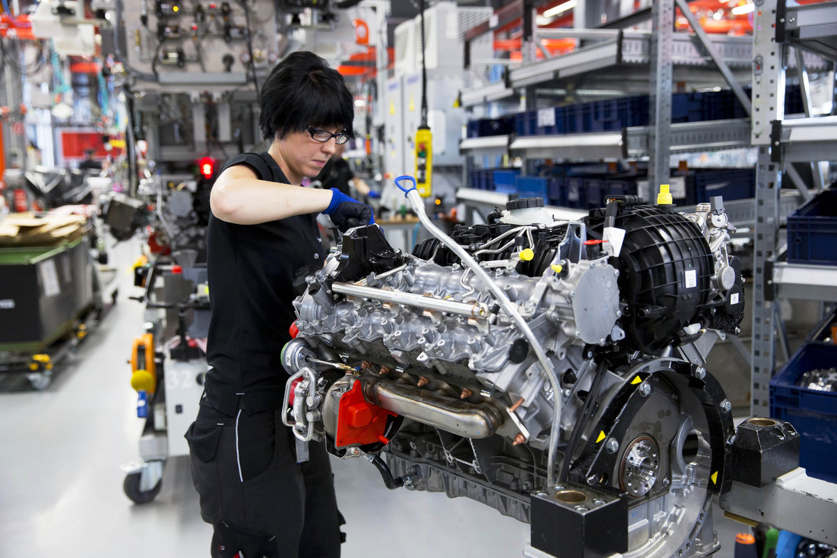
Multi-cavity tooling directly reduces per-part cycle time by producing multiple automotive components simultaneously from a single shot, maximizing press utilization. Integrating hot runner systems eliminates the need for cold sprue and runner recovery, as the melt remains fluid within temperature-controlled manifolds. This combination allows faster injection speeds and consistent packing across all cavities, minimizing overall cooling duration. For high-volume runs, balancing the runner geometry is critical to ensure equal fill rates, preventing overpacking or short shots that waste cycles. Hot runner thermal control further reduces cycle time by maintaining precise melt viscosity, enabling immediate part ejection without secondary cooling delays.
Multi-cavity tooling and hot runner systems achieve cycle time reduction through parallel part formation and eliminated cold runner cooling, optimizing each second for high-volume automotive production.
Minimizing Scrap Through Advanced Feed System Design
Advanced feed system design directly addresses scrap in high-volume automotive production by ensuring precise, balanced material flow to every cavity. Hot runner systems with individually controlled valve gates eliminate short shots and flash, while optimized gate geometry reduces shear stress that causes material degradation. This engineered precision dramatically cuts rejected parts from inconsistent fill. Minimizing scrap through advanced feed system design also relies on real-time pressure sensors to detect flow imbalances instantly, allowing autonomous adjustments before a single defective component is molded. The result is nearly zero-waste production runs.
Advanced feed system design eliminates scrap by delivering perfectly balanced material flow, reducing automotive injection molding waste to near zero.
Supplier Collaboration for Early Cost Targeting in Development
In high-volume injection molding, early cost targeting with suppliers demands integrating their process expertise during initial geometry design. By sharing target piece-part prices before mold steel is cut, engineers can select materials that minimize cycle times and avoid costly tooling complexity. Supplier input on gate locations, draft angles, and cooling channel layouts directly reduces per-part cost by eliminating later rework. This joint analysis of tolerance stacks and shrinkage rates ensures mold flow simulations align with real production constraints, preempting scrap and press downtime. The collaboration transforms the supplier from a vendor into a cost-engineering partner from concept through prototype validation.
Supplier collaboration for early cost targeting enables precise allocation of budget to material selection and tooling complexity, directly reducing high-volume unit costs through pre-production design alignment.
Emerging Technologies Reshaping the Production Landscape
For injection molded automotive components, digital twin simulation now allows you to virtually validate mold flow, cooling, and warpage before cutting steel, slashing physical trial cycles. Simultaneously, 3D-printed conformal cooling inserts enable complex internal channel geometries within molds, reducing cycle times by up to 50% and improving part dimensional stability. On the production floor, in-line cavity pressure sensors feed real-time viscosity data into adaptive process control algorithms, automatically adjusting hold pressures to counteract material batch variations. These sensor-driven systems integrate with AI platforms to predict tool wear patterns, scheduling preventive maintenance based on actual usage rather than fixed intervals, thus maximizing uptime for high-volume component runs.
In-Mold Decoration and Film Insert Molding for Custom Finishes
In-mold decoration (IMD) and film insert molding (FIM) enable custom finishes directly integrated during the injection molding cycle, eliminating secondary painting or plating. For automotive components like trim panels or bezels, a pre-printed carrier film is placed inside the mold cavity; molten resin then bonds to the film’s backside, creating a permanently fused surface with high abrasion and UV resistance. This process allows precise replication of metallic, wood-grain, or carbon-fiber textures without post-process defects.
- Pre-printed polyester or polycarbonate films ensure consistent gloss levels and pattern alignment across complex geometries.
- Eliminates VOC emissions from conventional liquid paint, improving workplace safety and cycle time.
- Supports tactile effects, such as soft-touch or textured haptics, by selecting films with engineered surface layers.
Integration of Sensors and Electronics into Molded Structures
The integration of sensors and electronics into molded structures transforms passive automotive components into intelligent, interactive systems. By overmolding conductive circuits onto polymer substrates during the injection cycle, manufacturers embed in-mold electronics directly into parts like instrument panels or door handles. This eliminates secondary assembly and reduces wiring harness complexity. The process follows a clear sequence: first, a decorative or structural film is placed in the cavity; second, conductive traces and microcontrollers are screen-printed onto that film; third, the thermoplastic resin is injected over the assembly, encapsulating the electronics. The result is a single, sealed component capable of touch sensing, haptic feedback, or real-time data transmission.
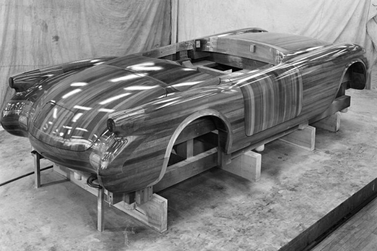
- Insert a functional film with pre-printed circuitry into the mold cavity.
- Deposit conductive vias and embedded sensor chips onto the film surface.
- Inject molten polymer to encapsulate the electronics and form the final structural part.
Predictive Maintenance Using IoT Data from Press Sensors
For injection molded automotive parts, predictive maintenance via press sensor IoT data quietly stops unplanned downtime before it starts. By monitoring parameters like clamp force, injection pressure, and temperature in real time, the system learns the specific “health signature” of each press. When sensor readings drift slightly—say, a subtle increase in cycle friction—the software flags the specific component likely failing, like a worn tie bar or valve. You then schedule a quick replacement during a planned shift change, not a frantic midnight firefight. This slashes scrap from sudden pressure drops and keeps critical trim or bumper molds running smoothly.
Regulatory Compliance and Industry Standards
For injection molded automotive components, regulatory compliance dictates material selection and process validation to meet industry standards like IATF 16949. This mandates strict control over flame retardancy and dimensional stability per specific client specifications. You must certify that molded parts, such as interior trim, pass FMVSS 302 for flammability. A critical detail to enforce is full traceability from resin lot to final assembled vehicle to support defect recall protocols. Adhering to ASTM D792 for density and ISO 527 for tensile strength is non-negotiable, ensuring every component withstands thermal cycling and vibration without failure, directly linking standard compliance to part safety and warranty risk management.
Meeting FMVSS and ECE Requirements for Interior Flammability
Meeting interior flammability compliance for injection molded components requires adhering to FMVSS 302 (U.S.) and ECE R118 (global), which mandate maximum burn rates. Material selection is the primary control: engineers must specify grades with halogen-free flame retardant additives that suppress ignition without compromising flow or impact strength. Process validation involves testing molded plaques in a horizontal burn chamber per test protocol. A clear sequence for compliance includes:
- Select a base resin (e.g., PP, ABS) with a flame retardant package rated V-0 or HF-1 per UL 94.
- Mold test specimens, noting that wall thickness below 2.0 mm may require higher additive loading.
- Conduct burn rate testing (
- Verify surface coatings or adhesives do not increase flammability beyond limits.
100 mm>
End-of-Life Vehicle Directives and Material Marking
End-of-Life Vehicle Directives mandate that injection molded automotive components be designed for efficient disassembly and recycling. Material marking per ISO 11469 and VDA 260 ensures every polymer part over 100 grams bears a permanent, legible identifier for its resin type and fillers. Correct material marking directly dictates recyclability and recovery rates. To comply, follow this sequence:
- Select moldable plastics from the approved recyclable materials list.
- Incorporate the standardized symbol and code into the mold tooling without compromising part strength.
- Verify marking permanence through heat and abrasion resistance tests.
Ignoring this coding can render entire modules non-recyclable under current take-back schemes.
Testing Protocols for Outgassing and Fogging in Cabin Parts
Testing for outgassing and fogging ensures cabin parts don’t release volatile compounds that cloud windows or cause odors. For injection molded components, we place samples in a sealed container with a cooled glass plate, then heat it to simulate a hot car interior. The fogging number—measured in milligrams—must stay below your OEM’s limit, often 1-2 mg. A gravimetric test checks the film’s weight on the plate, while reflectometer tests measure haze. Volatile condensable material testing is key here, as it directly mimics real-world sun exposure. Always run a blank first to rule out contamination from the test chamber itself.
Q: How long does a standard outgassing test take for a molded dashboard panel?
A: Usually 3 hours at 100°C, but some specs extend to 16 hours for thorough evaluation of low-molecular-weight additives.